It is impossible to imagine an electronic or electrical product today without an internal or external implementation of power conversion and processing solutions. These include sophisticated solutions and various diverse power supply topologies.
The two most common and simplest topologies in power supply voltage conversion are the BUCK CONVERTER and the BOOST CONVERTER, which are based on storing magnetic energy in an inductor and delivering it to the load.
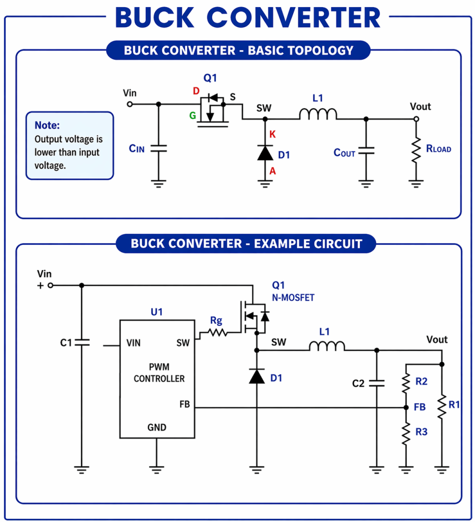
The BUCK topology allows the conversion of an input voltage to a lower output voltage without galvanic isolation between them (unlike the FLYBACK, which includes such isolation).
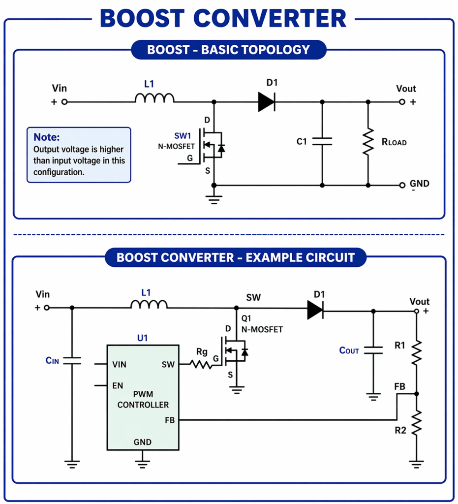
The BOOST topology allows the conversion of an input voltage to a higher output voltage without galvanic isolation between them (unlike the FORWARD, which includes such isolation).
At the heart of the BUCK or BOOST topologies lies the output inductor – the energy-storing element in the circuit that enables the conversion in combination with the PWM controller, which implements the voltage conversion ratio.
Proper design of the Output Inductor will ensure the proper operation of the circuit over time and good performance under various environmental conditions (temperature, humidity, barometric pressure, etc.).
The Output Inductor in BUCK CONVERTER and BOOST Topologies
The output inductor in the BUCK / BOOST topology stores energy in the first half of the switching cycle and releases it to the load in the second half. The inductor usually consists of a plastic frame (BOBBIN) on which the windings are wound.
In the center of the frame (BOBBIN), a ferromagnetic material (CORE) is usually assembled, which concentrates the magnetic field. This means it creates a concentration of magnetic flux lines (flux density B) to achieve the highest possible inductance in a given volume.
Additionally, the correct selection of the CORE and the winding wire will provide high efficiency (low thermal and magnetic losses), optimal volume, and low electromagnetic noise leakage. Proper design of the output inductor will also ensure low current ripple (Low Ripple).
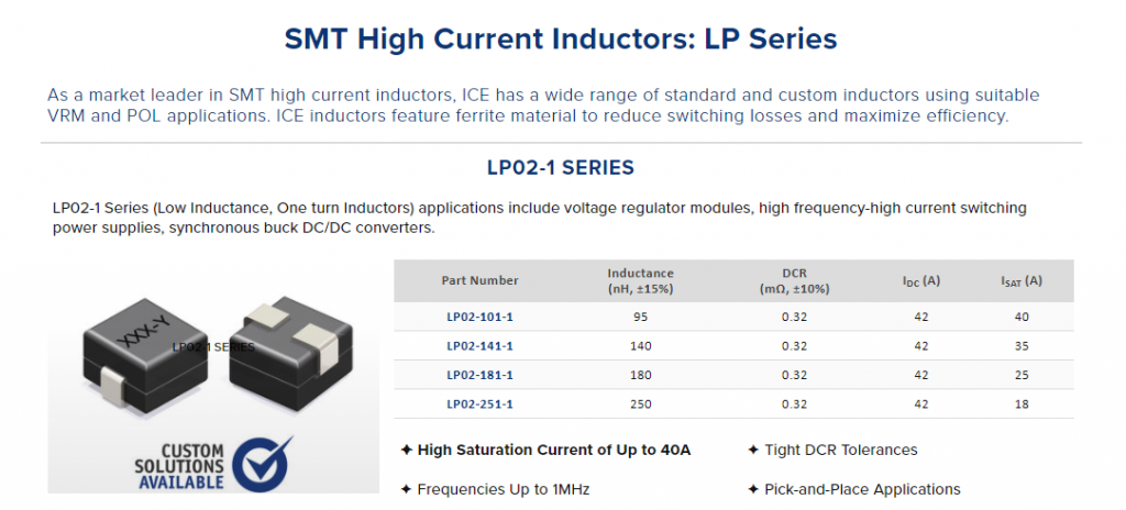
Figure 1: Typical BUCK / BOOST output inductor – low inductance for high switching frequency (1MHz-10MHz)
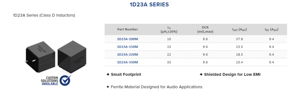
Figure 2: Typical BOOST / BUCK output inductor – high inductance for standard switching frequency (100KHz)
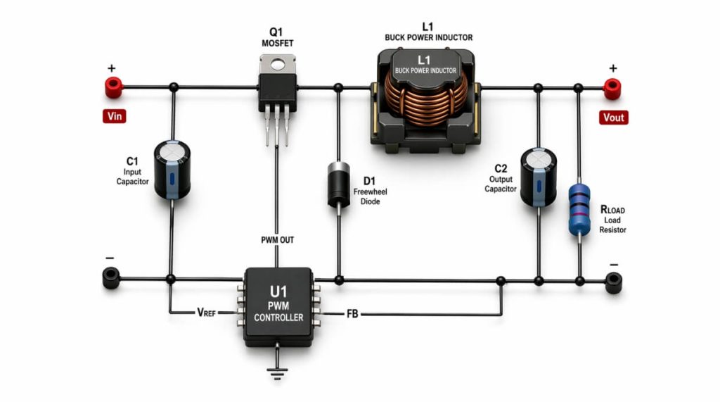
Output Inductor Integrated into a Typical BUCK Power Supply Circuit
Figure 3: Output Inductor integrated into a typical BUCK power supply circuit
Output Inductor Integrated into a Typical BOOST Power Supply Circuit
Figure 4: Output Inductor integrated into a typical BOOST power supply circuit
Advantages and Disadvantages of BUCK / BOOST Topologies
Advantages
Simplicity of design
Efficiency (low losses) of 90% and above
Reliability
Disadvantages
Switching noise and electromagnetic radiation (EMC)
Use of external components (capacitors, diodes)
Cost and board space
Design Principles of the Output Inductor
Choosing a BOBBIN
Based on the output current and the required inductance size (number of turns / type and size of the CORE), an appropriate BOBBIN is selected.
Choosing a CORE
Depending on the required inductance, various ferromagnetic materials can provide high inductance in a small volume (increased magnetic flux density B). A combination of different insulation techniques or the use of raw materials based on iron powder and glue will yield low losses (eddy currents / core losses). Correct selection of the CORE will also provide a flat inductance curve and saturation at a relatively high current.
Choosing the Winding Wire
The wire is selected based on the output current and the required losses (cross-sectional area, DCR resistance) to achieve maximum inductance and low losses.
Choosing the Package Type
The package type should allow for convenient assembly on the PCB (SMT / TH, Low profile). In cases where low electromagnetic radiation (EMC) is required, we will use Shielded (Monolithic) inductors.
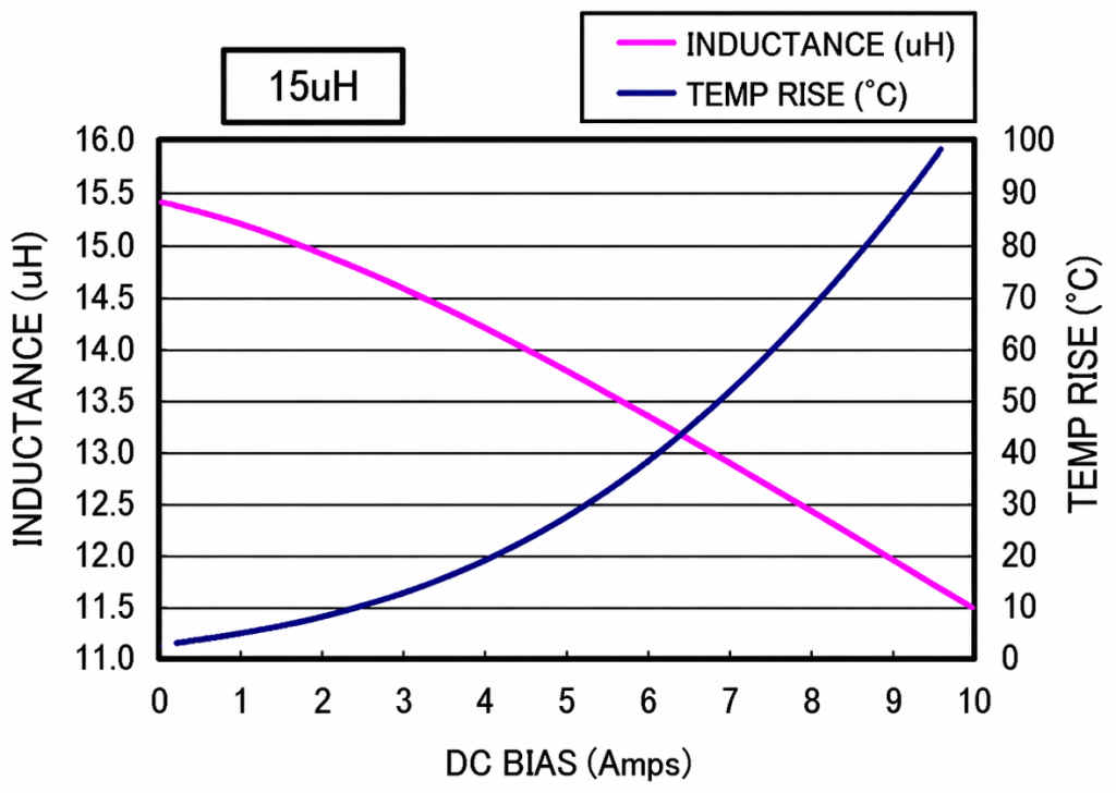
Figure 5: Output Inductor inductance dependence on output current, with the saturation knee on the right.
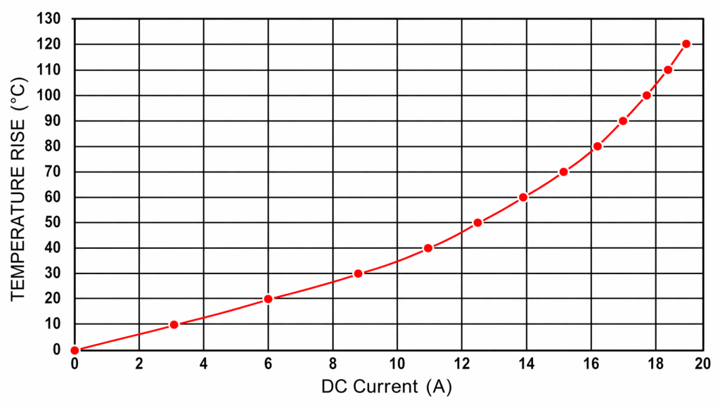
Figure 6: Output Inductor temperature dependence on output current (Temperature Rise)
Conclusion: Using an Output Inductor in BUCK and BOOST Converter Topologies
We can see that using a suitable and well-designed Output inductor, both in a BUCK topology circuit and a BOOST topology circuit, will ensure good circuit performance, along with parameter stability across temperatures and varying environmental conditions. A good output inductor will give us high inductance at our working frequency (switching) combined with delayed saturation (Saturation current) and a low temperature rise (Temperature rise ΔT/Amp).
Ronicon Engineering represents veteran Taiwanese companies that are leaders in the field of magnetics.
These companies have extensive experience in designing BUCK and BOOST inductors, and they know how to adapt these inductors to customer requirements. Furthermore, with the help of the magnetics manufacturers’ engineers, we provide consultation for the optimal design of the electronic circuit.
You can contact us through our website, and we will quickly direct you to our engineers for support and consultation.
Cookies & Privacy.
We use only essential cookies to make this catalog work. With your permission, we'd also like to enable
analytics cookies that help us understand how visitors use the site. You can change your choice anytime in our
Cookie Policy.