Most electrical products sold today require sophisticated power conversion and processing solutions, along with various diverse power supply topologies. One of the most common topologies for power supply voltage conversion is the FLYBACK.
The FLYBACK topology allows the conversion of an input voltage into multiple (lower) output voltages, at a medium power of several tens of WATTs, while creating galvanic isolation between the input and output (including isolation between a high voltage of hundreds of volts and a low voltage of just a few volts).
At the core of the FLYBACK topology is the transformer, whose turns ratio, combined with the PWM controller, implements the voltage conversion ratio. Proper design of the FLYBACK transformer will ensure the proper operation of the circuit over time and good performance.
The Flyback Transformer
The FLYBACK transformer generally consists of a plastic frame (BOBBIN) on which the various windings – primary and secondary – are wound. The transformer manufacturer uses different insulating materials to insulate the winding wires as well as partitions between the layers.
There are also different winding methods – all designed to create galvanic isolation between the input and output without significantly impairing the transformer’s performance.
In the center of the frame (BOBBIN), a ferromagnetic material (CORE) is usually assembled, which concentrates the magnetic field and creates a strong coupling between the layers for optimal energy transfer from the input to the output.
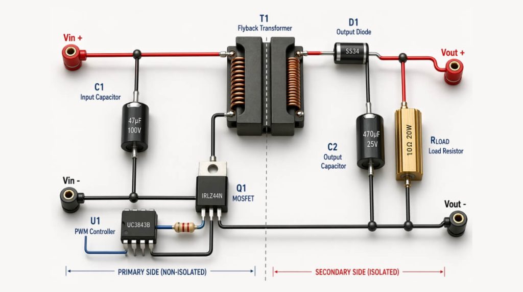
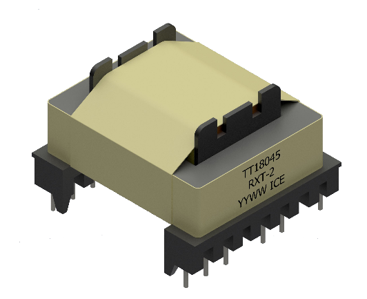
Figure 3: Typical FLYBACK TransformerFigure 4: FLYBACK Transformer integrated into a typical power supply circuit
Advantages and Disadvantages of the FLYBACK Topology
The FLYBACK topology brings the following advantages:
Simplicity of design (similar to the BUCK topology).
Multiple voltage outputs.
Galvanic isolation between the power supply’s input and output.
The main disadvantages are:
Lower efficiency than the BUCK due to the use of a transformer with core losses and ohmic losses.
Relatively slow response times (1-5Khz bandwidth).
Lower voltage accuracy than the BUCK, especially in outputs that do not receive FEEDBACK.
Additional Disadvantage
A minimum load must be used; otherwise, the output voltage rises to excessively high levels and may damage the output capacitors (this is usually implemented using load resistors, which reduces efficiency).
Because the advantages outweigh the disadvantages, and mainly due to its simplicity of implementation and low cost, the FLYBACK topology is very common in the industry.
Design Principles of a FLYBACK Transformer
The FLYBACK transformer is characterized by several key features. High-quality manufacturing and close attention to these features will ensure good power supply performance (efficiency, voltage accuracy, good response times, and low EMC radiation). The manufacturer will typically attach measurement results and a full characterization of these parameters to the datasheets of the ordered component (usually custom-made).
Efficiency
Assume an efficiency of 70% – 85% and define the output power; from this, define the input power.
Ripple Current
Given the input ripple current limit and assuming a maximum Duty-Cycle of 45%, the input inductance will be defined. Based on the input inductance, the switching frequency, and the required efficiency, the CORE will be selected.
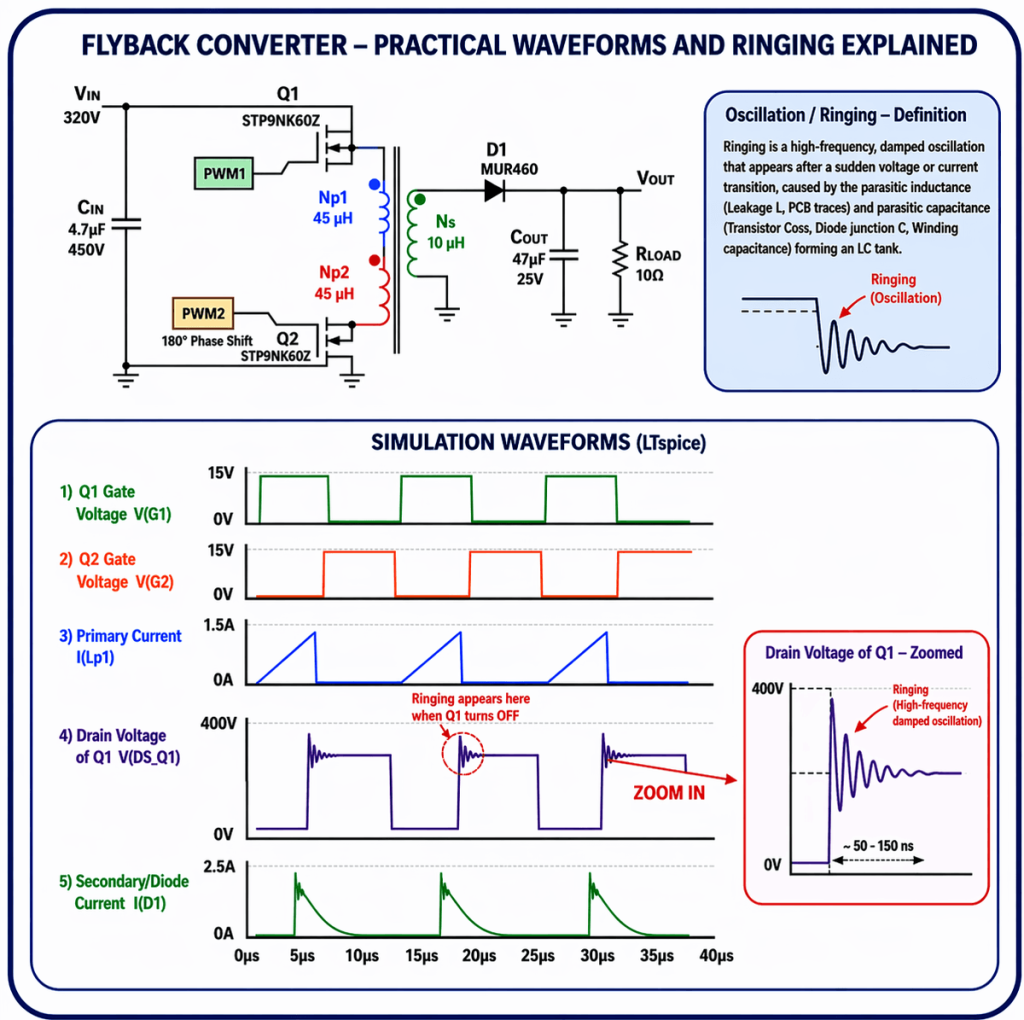
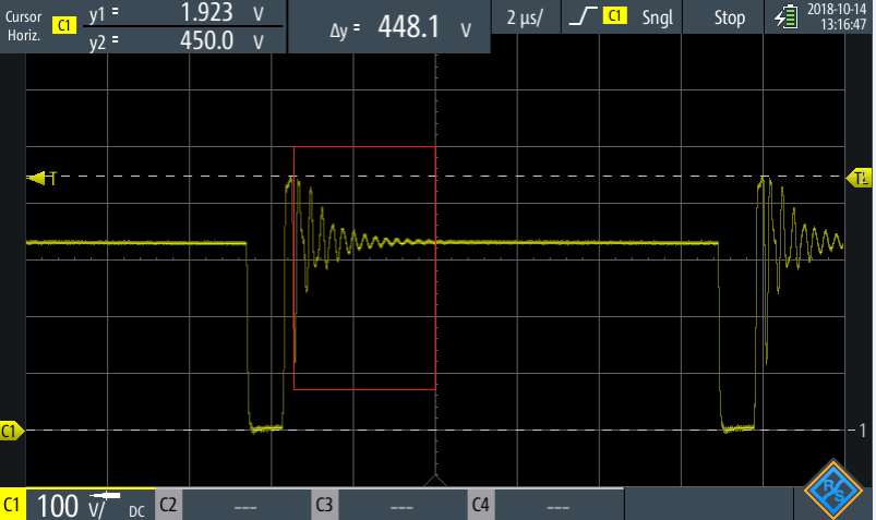
Parasitic Inductance – Leakage Inductance
This will be reduced to a minimum (1-10 or 1-20 of the input inductance) to minimize power waste as much as possible and allow for a minimal SNUBBER to reduce RINGING during T-OFF (the half cycle in which the SWITCH is disconnected).
Figure 5: The effect of LEAKAGE INDUCTANCE on the Vds voltage of the Switch
Input Current
After calculating the maximum input current, calculate the minimum number of primary turns (Np) at the input to prevent magnetic saturation in the chosen CORE.
Given the number of primary turns (Np) of the FLYBACK, the number of secondary turns (Ns) for all outputs will be defined according to the voltage ratio and a Duty Cycle of 45%.
Winding Wires
The thickness of the wires in the secondary windings will be selected according to the maximum output current, the reduction of the SKIN EFFECT (using multiple parallel windings of a thinner wire), and the available winding window.
We will require the manufacturer to separate the primary and secondary windings from each other to reduce parasitic capacitance.
Insulation Between Layers (HI-POT)
We will require the manufacturer to provide insulation levels and breakdown voltages according to our product’s specifications or the required standard.
HI-POT, for example: 2500V AC, 60Hz, 3mA, 2sec. Sometimes, insulation for DC voltage is also required (dielectric strength).
Environmental Conditions
We will require the manufacturer to use materials and a design that enable compliance with various environmental conditions, as required by our product specifications.
Using a Flyback Transformer – Conclusion
We can see that using a suitable and well-designed Flyback transformer will ensure good circuit performance, along with parameter stability across varying temperatures and environmental conditions.
Ronicon Engineering represents veteran companies with extensive experience in designing FLYBACK transformers, and they know how to adapt the FLYBACK transformer to customer and standard requirements.
Furthermore, with the help of the magnetics manufacturers’ engineers, we provide consultation for the optimal design of the electronic circuit. You can contact us through our website, and we will quickly direct you to our engineers for support and consultation.
Cookies & Privacy.
We use only essential cookies to make this catalog work. With your permission, we'd also like to enable
analytics cookies that help us understand how visitors use the site. You can change your choice anytime in our
Cookie Policy.