Almost every modern power circuit incorporates a current measurement mechanism / current sensor. Such a mechanism allows continuous monitoring of the system’s integrity and prevention of overheating (Thermal Runaway).
This is achieved by tracking, at various levels of accuracy, the actual current intensity passing through the system’s conductors, and especially the system’s input lines (Bus Bar).
Another application of a current measurement mechanism / current sensor is to implement a current loop (closed control loop) in applications that require it, such as DC / AC Brushless motors, and power supplies with current control.
Proper circuit design, combined with a reliable and accurate current sensor, will ensure the proper operation of the circuit over time and excellent performance under various environmental conditions (temperature, humidity, barometric pressure, etc.).
The Current Sensor
The role of the current sensor (CS) is to convert the current flowing in the measured circuit or supply line into an analog electrical voltage or another electrical signal—for example, variable frequency or variable Duty Cycle. This allows the Microcontroller to “sense” the current intensity in the circuit and perform various calculations on it.
The common methods in the industry for current sensing are: a current transformer / sensor based on a current loop, or a sensor based on the HALL effect. ICE’s ISB series sensors are HALL-based sensors.
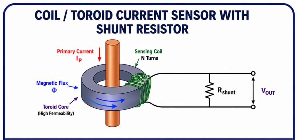
Figure 1: Current sensor based on a coil / toroid and current loop
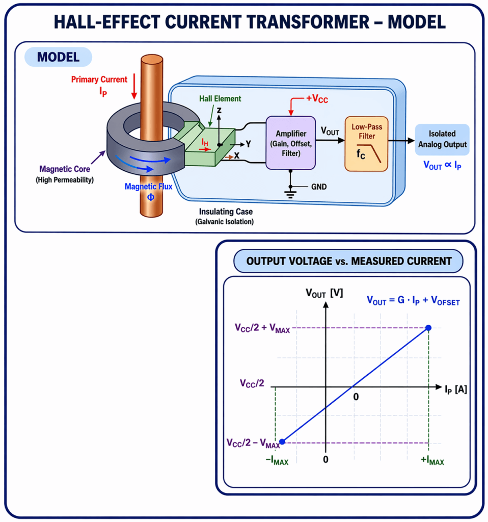
Figure 2: Current sensor based on the HALL effect
Principle of Operation of a HALL Sensor
Current flowing in a conductive wire induces a magnetic field in the Core and creates a HALL voltage. This field, combined with a constant supply current source (Ic), causes the HALL sensor to operate at a fixed operating point. This creates linearity between the measured conductor current and the output voltage Vo.
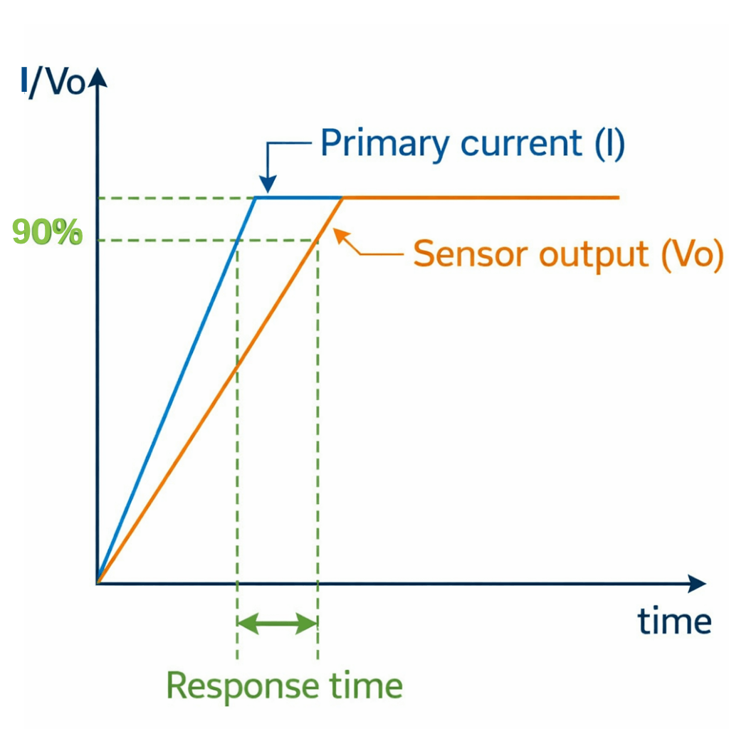
Figure 3: Dependence of output voltage Vo on the measured current (linearity) and response time
Advantages and Disadvantages of HALL Technology
Advantages:
Simplicity of design
High efficiency
Reliability
Accuracy
Small physical volume
Disadvantages:
Sensitivity to noise (requires shielding or distancing from noise sources).
Temperature dependence (requires calibration).
Requires accompanying electronics for the Ic current source (this is usually integrated within the sensor itself, including the amplification between the HALL voltage and Vo).
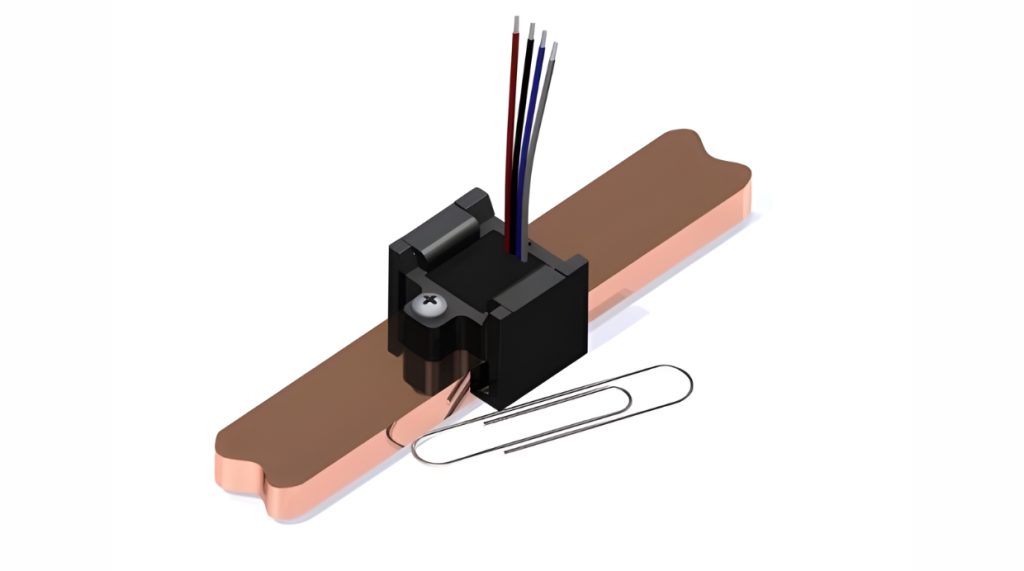
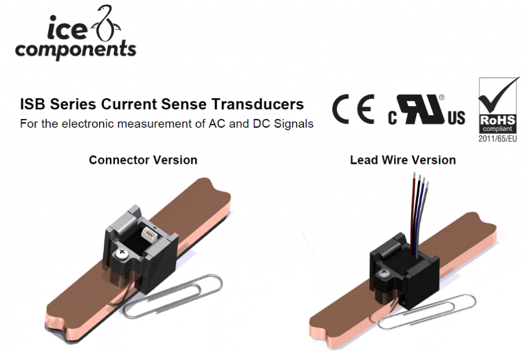
Figure 4: Current sensor based on the HALL effect from ICE’s “ISB” series
ICE’s “ISB” series sensors cover a wide current range: from +/- 100A to +/- 670A.
These sensors are enclosed in a shielded package (SHIELD), which allows the concentration of magnetic flux lines close to the HALL sensor. This enables the measurement of particularly weak currents with high accuracy (0.6%), even at a distance of only 12.7mm from strong current lines.
These sensors excel in a high isolation level for breakdown voltage (4kV and more) as well as fast response times (3-8usec). Various sensor options provide additional signals, such as a REFERENCE voltage (Vdd/2) for an ADC, as well as an analog output that varies linearly with the sensor’s temperature.
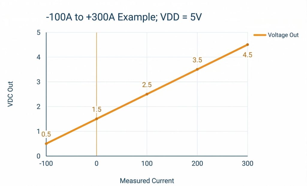
Figure 5: Example of linearity in measuring an asymmetrical current (+300A / -100A) using an ICE ISB sensor
Design Principles for a HALL-Based Current Measurement Mechanism
Define the maximum current we need to measure, as well as the symmetry around 0A (yes or no).
Choose a current sensor (ISB) that covers the measured range well, leaves design margins (at least 30%), and meets the required accuracy level (sometimes calibration will be required after assembly). It is crucial to work within the linear range of the sensor (Ip).
Check the mechanical size compatibility with the system’s requirements.
If necessary, order custom sensors that provide a tailored transfer graph, dynamic range, and output voltages.
Verify the compatibility of the sensor’s supply voltage with our system (for example, 5V / 12mA).
Perform laboratory measurements after assembling the sensor and apply calibrations as required to ensure compliance with the design requirements.
Perform measurements at different temperatures to verify if an automatic compensation or calibration mechanism is required.
Conclusion: Using a Current Sensor
We can see that using an appropriate and well-designed Current sensor ensures good circuit performance, along with parameter stability across varying temperatures and environmental conditions. Selecting a component from the ISB series provides the designer with a large dynamic range, temperature stability, measurement accuracy, and robust noise immunity at a relatively short distance from noisy supply lines.
The engineers at Ronicon Engineering have extensive experience with this type of design and know how to adapt the Sensor to customer requirements.
You can contact us through our website, and we will quickly direct you to our engineers for support and consultation.
Cookies & Privacy.
We use only essential cookies to make this catalog work. With your permission, we'd also like to enable
analytics cookies that help us understand how visitors use the site. You can change your choice anytime in our
Cookie Policy.