Proper design of a Power Line Choke and Ferrite helps us reduce emitted radiation to permissible levels. Most electrical products sold today, both for domestic and industrial use, are required to meet strict Electromagnetic Compatibility (EMC) conditions.
As part of the testing and certification process, the designer is required to demonstrate low levels of radiation emission as well as immunity to high radiation levels that affect the proper operation of the product. In high-power/inherently noisy systems such as industrial motor controllers or switched-mode power supplies, the product certification process, especially the requirement to limit emitted radiation, becomes a real challenge.
For more on the proper design of a Power Line Choke and Ferrite to meet strict Electromagnetic Compatibility (EMC) conditions, keep reading.
Main Deviations in EMC Testing
Performing tests during the design phase usually reveals noise in the frequencies of (150Khz – 30Mhz – CE testing) and frequencies of (30Mhz – 3Ghz – RE testing).
FERRITE & CHOKE: Common Methods for Solving Deviations
There are techniques which, by using appropriate components—and in addition to a clean and correct design—make it possible to pass the tests in a relatively short time and with good results.
The FERRITE
A component with a core made of ferromagnetic material (concentrating flux lines) that provides a high impedance to noise and routes it to nearby grounds.
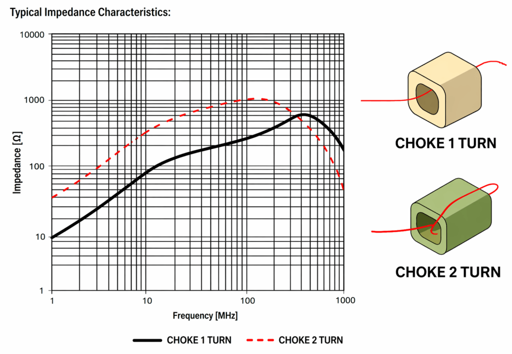
There are Ferrites made of various materials, and this, combined with the winding of the noisy lines, prevents the noise from being emitted from the system. Different materials and different geometric structures affect the blocking frequencies of the FERRITE.
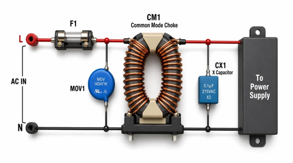
The POWER LINE CHOKE
The Power Line Choke is generally used to attenuate low frequencies in the system’s power supply lines.
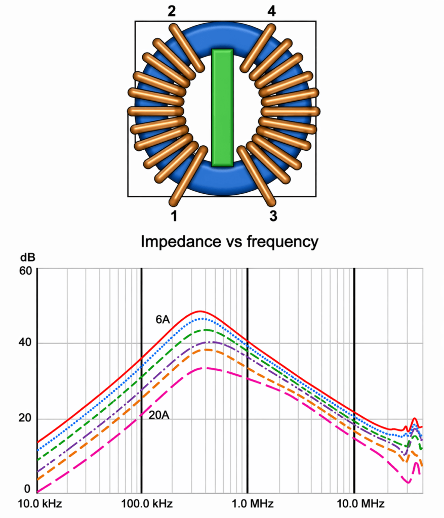
The CHOKE consists of winding the supply lines on a core made of ferromagnetic material. Such a winding allows the system to receive the supply (differentially) properly, while at the same time, COMMON MODE noises are attenuated extremely efficiently.
The effective frequency range of the CHOKE is usually 100Khz – 1Mhz and depends on the type of core, the number of windings, and its geometric structure. Additional parameters to consider are: the self and mutual inductance of the CHOKE and its saturation current.
It is worth noting that ICE (Taiwan) is one of the leading manufacturers in the field, with a complete product line for solving EMC problems.
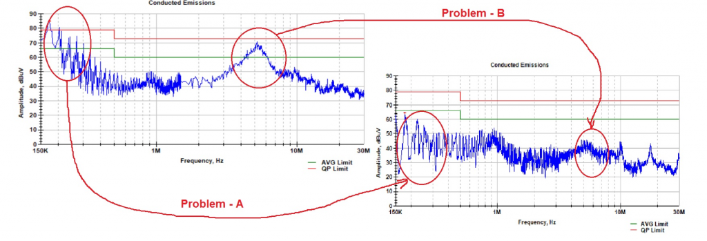
Deviation A
Low frequency around 170Khz; the use of a Power CHOKE brings an improvement of about 20dB and the test passes.
Deviation B
A frequency of about 5Mhz; the use of a FERRITE adapted to this frequency, combined with 3 windings, brings an improvement of about 30dB.
Using a Power Line Choke – Conclusion
We can see that using an appropriate Power line choke makes it possible to significantly reduce EMI deviations and meet the required standards. The engineers at Ronicon Engineering have extensive experience in solving these types of problems and know how to adapt the Power line choke according to the standard’s requirements.
You can contact us or reach out directly to ICE through our website, and we will quickly direct you to a leading engineer in the field of your inquiry for support and consultation.